STANDARD HANGAR WITH LSTS FRAME
1. OUTPUT DATA
Considering standard universal hangar with a range of intended purposes:
Warehouse
Structure of agricultural use
Manufacturing or auxilliary rooms
Other designations, according to the volumetric-planning option of this building with no overhead traveling cranes
The project is recommended for agricultural use because of galvanized coating of the building frame.
Construction site location: Kyiv Oblast
Above mean sea level on the site: less than 500 m
Local relief at the construction site: flat
Type of construction: new construction
Difficulty category — III
Consequence class — CC2
Criticality-based safety factor according to Table 5, DBN V.1.2-14-2009: γn = 1.05 for the first group of limit conditions, 0.975 — for the second
Design-based operating life according to Table 2, DBN V.1.2-14-2009: Tef = 60 — 50 years (depending on the type of operating conditions: industrial, warehouse, or agricultural)
Overall dimensions — 36.00 m х 12.00 m
Warehouse building — ventilated, with thermal insulation and independent heating
The slope of roof — 10% (sandwich panels)
Finished hangar floor mark is considered as relative mark 0.000
These structures are recommended for use in non-aggressive, weakly aggressive, and medium aggressive environments in climatic regions with ambient air temperatures within the range of -40°С ÷ + 40°С.
The main selection criteria for structures are enlargement of spans, general construction cost reduction, and shortening of construction completion time.
The overall structure must be made of materials manufactured at Ukrainian plants.
These structures are intended for use in the following climatic regions:
Snow loads — 5th region (as per DSTU-N B EN 1991-1-3)
Wind load — 2nd region (as per DSTU-N B EN 1991-1-4)
According to DSTU-N B EN 1998-1-1, it is accepted that the construction site belongs to a zone of low seismic activity (ground acceleration does not exceed 0.04g).
Other special conditions of the construction site (sinking in soils and wetland areas) — not present.
frame calculations are carried out based on the following:
DSTU-N B EN1990 "Basics of Structural Design"
DSTU-N B EN 1991-1-1 "Actions on Structures. Specific Weight, Steady and Temporary Loads on Buildings"
DSTU-N B EN 1991-1-3 "Actions on Structures. Snow Loads"
DSTU-N B EN 1991-1-4 "Actions on Structures. Wind Loads"
DSTU-N B EN 1993-1-1 "Structural Steel Design. General Rules for Buildings"
DSTU-N B EN 1993-1-3 "Structural Steel Design. Supplementary requirements for profiles and floorings made using cold molding"
DSTU-N B EN 1998-1 "Design of Structures for Earthquake Resistance. General Rules, Seismic Actions, and Rules for Buildings"
2. ARCHITECTURAL AND PLANNING CONCEPTS
General characteristic of a buiding
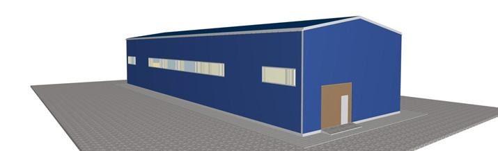
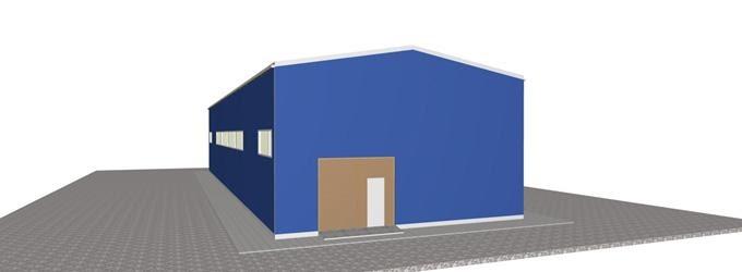
The volumetric planning and design concepts of a hangar shall conform to the intended performance.
Universal standard frame hangar with overall dimensions of 36.00 m х 12.00 m. Building — one-storey, rectangular, total floor area of 432 sq. m.
Roofing — gable.
For the building design, the following parameters were accepted:
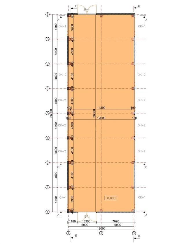
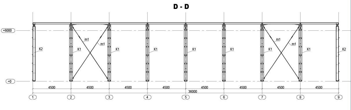
In the longitudal direction, a frame span of 4.50 m
In the transverse direction, a single span of 12 m
Heigh to the bottom of support structures is 6.0 m
Materials belonging to the class of non-combustibles in cold conditions may be used in a building.
According to the selected category and adjusted for the floor surface area (see Table 2, DBN V.2.2-7-98), the fire-resistance rating of the warehouse is IIIa.
Volumetric planning concept
The hangar's planning concept specifies one main room with a surface area of 432 sq. m.
Walls and roofing are thermally insulated as per DBN V.2.2-7-98. Walls - internal wall cassette (IWC), 600 /150х0.75 mm, insulator - 150 mm, external profiled flooring, Т10 0.45 V. Roofing — sandwich panels with PU foam filling, 100 mm thick.
Flooring as per technical specifications. In the standard option — according to SNiP 2.03.13 and DBN V.2.2-7-98: asphalt-concrete, and if there is no impact of acid solutions — concrete.
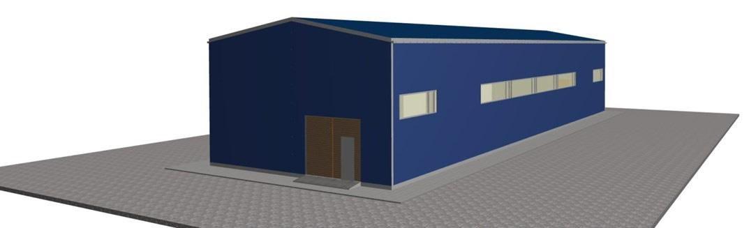
Windows — to ensure natural light and ventilation, as an option, are located in the upper section of external walls, at a 3.0 elevation mark from the surface, adjusted for vertical connections in Axes 2-3 and 7-8 in the longitudinal direction. Windows of the continuous type:
ОК-1 - 3.50 х 1,20 (N) m - 4 pcs.
ОК-2 - 4.00 х 1.20 (N) m - 8 pcs.
Doors and gates - in short sides along Axes "A" and "V", according to technical requirements, two standard hinged metal gates with the overall dimensions of 3.50 х 3.00 (N) m with a separate gate for evacuation of the hangar's service personnel, with the dimensions of 0.80 х 2.10 (N) m. The separate gate is without sills (or, as an option, with sills of maximum height of 0.1 m), to be opened outward. Doors and gates must be equipped with locks and bolts.
Columns and passageway framing must be protected with non-metal materials against mechanical damage in places of intensive overland traffic.
The warehouse walls must be painted with bright lines and signs; in addition, requirements to supervision, operation, and organization of qualified mechanization of loading works must be observed.
The surface area of the hangar room is 428.80 sq. m
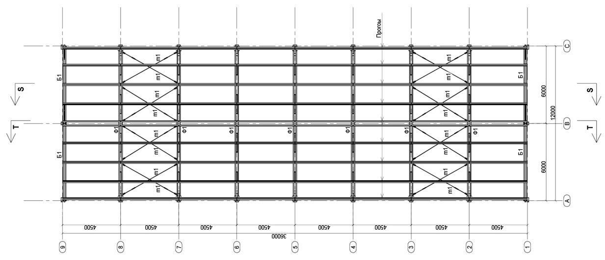
Plan at Elev. +0.000
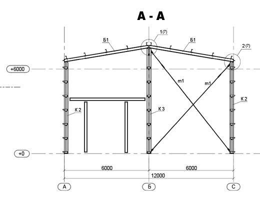
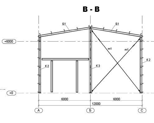
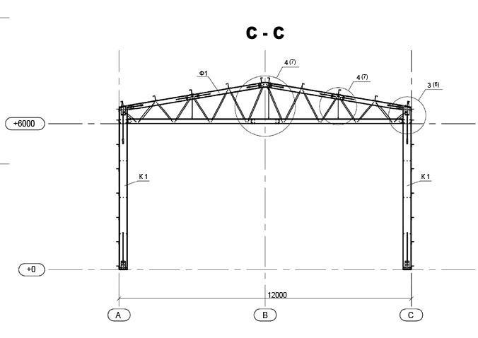
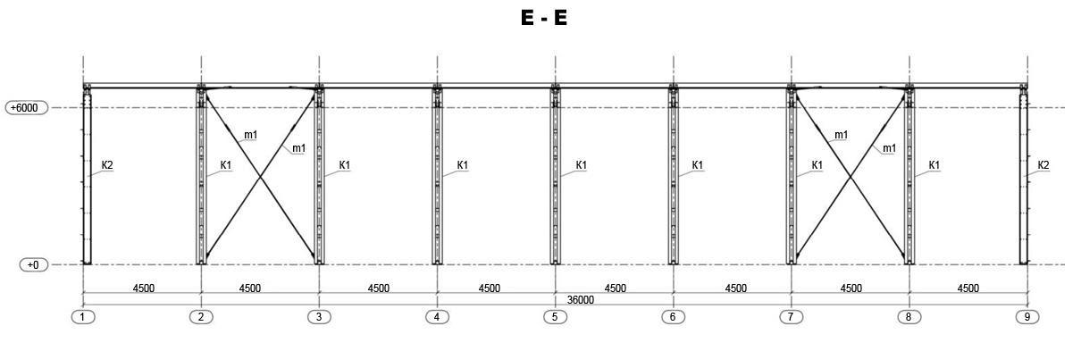
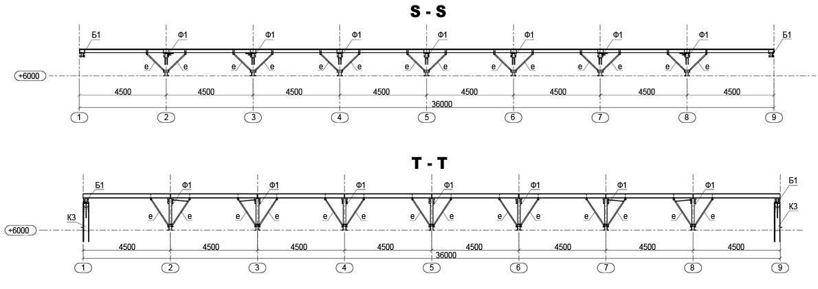
Cross-sections
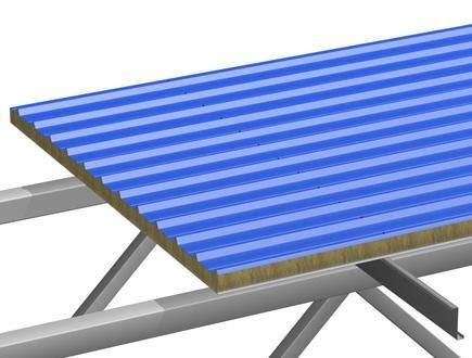
Roofing design
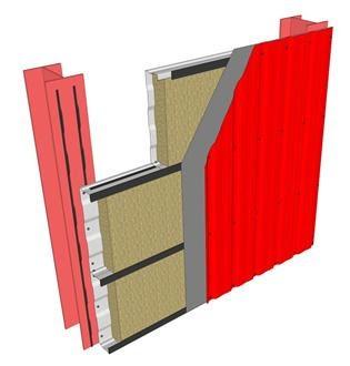
Wall design
3. CONSOLIDATED SPECIFICATIONS OF MAIN FRAME STRUCTURES
Adjusted for the strength-weight ratio, the total weight of metal structures is 11.10 tons.
In particular:
The girder of loadbearing frames, 4.000 tons
Columns of loadbearing frames, 3.000 tons
Side framing, 1.200 tons
Roofing spans, 2.100 tons
Vertical and horizontal connections, 0.500 tons
Gate underframes, 0.300 tons
In total, 11.10 tons
The total building area is 432 sq. m., therefore, the specific quantity of metal per frame is 11300/432 = 25.7 kg / sq. m.
4. LOADS AND INFLUENCES
Frame calculations are performed according to Eurocode 3 (DSTU-N B EN 1993) "Structural Steel Design", and, in particular, Part 1-3 (DSTU-N B EN 1993-1-3) "Structural Steel Design. Additional rules for cold-molding items and profiled sheeting".
Accordingly, Loads and influences are calculated by Eurocode 1 (DSTU-N B EN 1991), and are determined as follows:
Material | Distribute load (kPa) | Specific weight (T /cub. m) | Thickness (m) | ɣF |
PU foam sandwich panels with a 100 mm thick filling | 0.150 | - | - | 1.35 |
Additional load from hook-up items | 0.250 | - | - | 1.35 |
Operating load 0.400 kPa
Critical load 0.540 kPa
Snow load (calculated according to the design standard DSTU-N B EN 1991-1-3)
Parameter | Value |
Snow region | 5 |
Characteristic snow load value | 1.6 kPa |
Adjustment ratio for the mean return perion Tef = 50 years | 1.00 |
Wind load (calculated according to the design standard DSTU-N B EN 1991-1-4)
Parameter | Value |
The region, chosen by the characteristic value of basic wind velocity | 2 |
The characteristic value of basic wind velocity | 27 m/s |
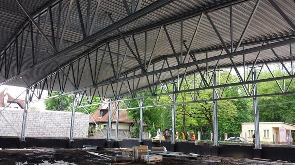
5. STRUCTURAL LAYOUT
The building's structural layout is a braced frame structure
The support structure is based on transverse frames with rigid "truss-column" connection with hinged foundation support. This layout is typical for pavilion-like buildings with no overhead traveling cranes and provides an optimal weight with minimal foundation load. Frames are single-spanned, 12 m within axes. The frame construction is made of thin-walled cold-molding profiles (LSTS).
Manufacture and installation of building structures shall conform to:
DSTU B EN 1090-1 "The implementation of steel and aluminum structures. Part 1. Requirements for conformity assessment of structural components"
DSTU B EN 1090-2 "The implementation of steel and aluminum structures. Part 2. Technical requirements to steel structures"
EN 10162 "Cold-rolled steel profiles. Technical specifications. Margins for dimensions and cross-sections"
The flooring support structure for intermediate frames is gridlike, for side framing — beams made of twin 3-profiles. The crossings of columns with main and side frames are made of C-shaped profiles. Vertical binding by columns, and horizontal by flooring, are made of X-shaped flexible preloaded (by struts) items.
Longitudinal vertical column binding provides for volumetric rigidity in the longitudinal vertical direction. Rigid transverse intermediate frames with ties to columns and vertical binding inside framing provide for volumetric rigidity in the transverse vertical direction.
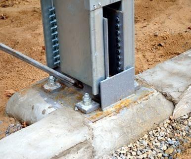
An example of flexible joint preloading
Horizontally, the frame is tied up with a rigid covering formed by a system of horizontal and vertical ties along the covering surface. Horizontal ties are flexible, preloaded. Vertical ties form steel strap braces (struts) and tie up the lower chord beams.
The building is warm. The wall structure is made with no binding beams. Cold-moulded galvanized profiles of internal wall cassettes (IWC), 600 / 150 х 0,75 mm, provide support for enclosure structures. Thermal heating is done with mineral wool filling 150 mm thick. From a designer's point of view, one positive effect of IWC is a significant increase of frame strength to horizontal loading.
The roofing structure is interconnected beams. Enclosure structures are sandwich panels with 100 mm thick PU foam insulation. Beams are cold-formed galvanized Z-shaped profiles placed by the split design principle.
Alternatively, the "cold" option of the building is available for consideration
Structural design of roofing
Factory-made connections — by welding and bolts, on-site connections — by bolts. Welded joints are done with semiautomatic welding equipment. Bolted connections are done with bolts of strength grade 8.8. Bolted connections are protected against unfastening.
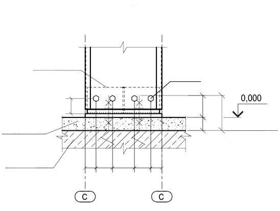
The building foundation — depending on the technical specifications and geological properties, construction sites may be located separately, be continuous, plated with or without piles. Base plates are filled with mortar immediately after fitting and mounting of base plates, and before mounting the scape.
Material for mainframe items made of cold-formed profiles is hot-galvanized coiled steel of Grade S350GD up to 3 mm thick. Shaped and auxiliary items are made of steel of grade S245.
6. CORE COMPONENTS
Standard column base
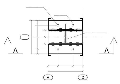
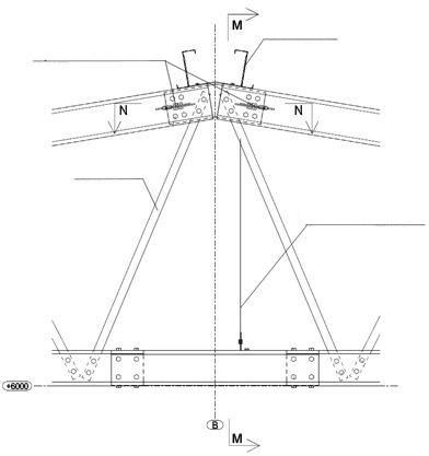
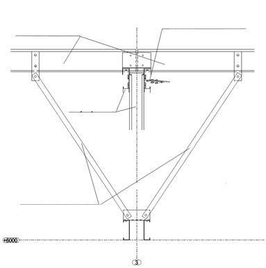
Ridge-type joint with vertical and horizontal fastening elements
7. FIRE AND RUST PROTECTION OF STEEL STRUCTURES
The building is assigned fire-resistance rating IIIa. To meet the relevant requirements, it is necessary to ensure the following design components have an adequate fire-resistance rating:
Columns — R15 M0
Components of superimposed covering (plates, flooring, girding beams) — RE15 M1
Components of superimposed covering (beams, frames, arcs, trusses) — RE15 M0
External non-supporting walls — E15 M1
According to par. 4.40 DBN V.1.1-7, fire protection of steel structures may not be provided if the minimal fire resistance limit of a given structure does not exceed 15 min.
Structures with a fire-resistance limit of at least (EI30, M0) are recommended for enclosure structures of walls; these limits must be confirmed by a product certificate. For LSTS, it is recommended to use structural fire protection as the main method if fire resistance requirements are raised.
Zinc coating of all cold-formed frame profiles provides corrosion protection for building structures. The recommended specific weight of zinc coating is 275 g /sq. m.
The facility is standard and can be used for different purposes. Simple zinc coating of main components permits the aggressiveness of environmental impact on metal structures as per EN ISO 12944-2 no more than C3 (moderately corrosive). If the environment is highly corrosive, it is recommended to build support structures on the outside of a building (this way, the environmental impact should be eliminated).
This layout is widely used for poultry houses (a highly corrosive environment) and clod storage warehouses (exceptions are thermal bridges, sealing of refrigeration chambers).